Accuracy Check of the Measuring Tool
The following tasks should be performed only by well-trained and qualified persons. The legalities with regard to performing an accuracy check or calibration of a measuring tool must be known.
Influences on Accuracy
The largest influence is exerted by the ambient temperature. In particular, temperature differences that occur from the ground upwards can refract the laser beam.
In order to minimise thermal influences resulting from heat rising from the floor, it is recommended that you use the measuring tool on a tripod. In addition, position the measuring tool in the centre of the work surface, wherever this is possible.
In addition to external influences, device-specific influences (e.g. falls or heavy impacts) can also lead to deviations. For this reason, check the levelling accuracy each time before beginning work.
If the measuring tool exceeds the maximum deviation for the measuring procedures described below, perform a calibration see Calibrating the measuring tool or have the measuring tool checked by a Bosch customer service agent.
Checking the levelling accuracy in a horizontal position
For a reliable and precise result, it is recommended that you check there is a free measuring distance of 30 m on firm ground in front of a wall. Carry out a complete measuring procedure for each of the two axes.
- Mount the measuring tool in a horizontal position 30 m from the wall on a tripod, or place it on a firm, level surface. Switch on the measuring tool.
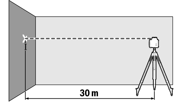
- Once levelling is complete, mark the centre of the laser beam on the wall (point Ⅰ).
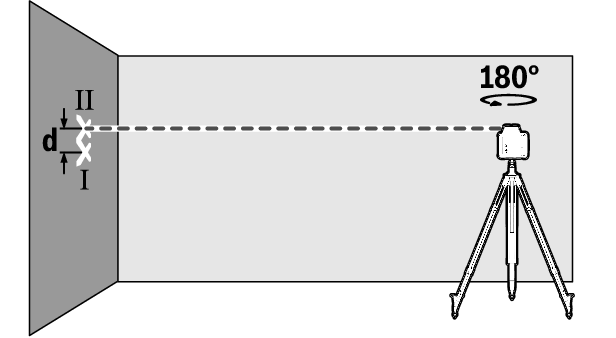
- Rotate the measuring tool 180° without changing its position. Allow it to level in and mark the centre point of the laser beam on the wall (point Ⅱ). Note that point Ⅱ should preferably be positioned vertically above or below point Ⅰ.
The discrepancy d between the two marked points Ⅰ and Ⅱ on the wall reveals the actual height deviation of the measuring tool for the axis being measured.
Repeat the measuring process for the other axis. To do this, turn the measuring tool by 90° before beginning the measurement.
The maximum permitted deviation on the 30 m measuring distance is as follows:
30 m × ±0.05 mm/m = ±1.5 mm. The discrepancy d between points Ⅰ and Ⅱ must therefore amount to no more than 3 mm for each of the two measuring processes.